
THE ARMOUR
OF COMMERCE.
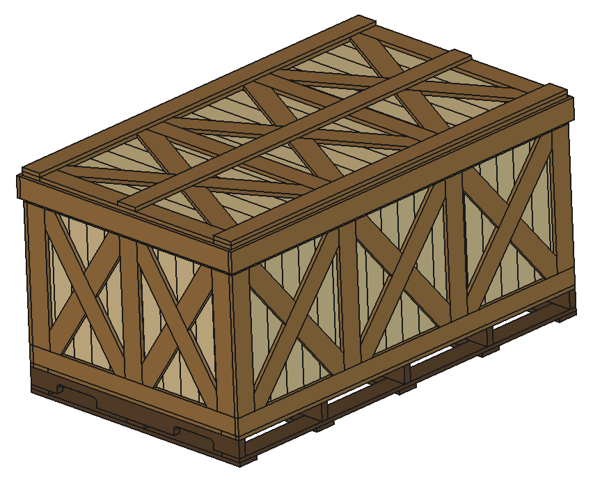
A transport crate is not a box — it is a computed structure: a lattice of boards engineered board-by-board to carry a specific machine, across a specific route, at a specific weight. This page walks through everything the engine decides for your freight, and how to finish and seal the crate so the cargo arrives exactly as it left.
01What a Transport Crate Is
In its etymological sense, the word “crate” descends from the Latin cratis — a lattice or grating. It was never a sealed box; it is a pattern of boards engineered to resist the forces of the road, the ship and the sky. That is exactly what we sell: the pattern, computed for your cargo, delivered as a blueprint.
Our parametric engine designs the crate around three numbers you provide — exterior length, width and height in millimetres — plus your material source, wall mode and handling needs. From those three numbers it derives every member of the lattice: posts, rims, braces, slats, skids and the lid, each sized and positioned with engineering logic rather than habit.
The result is a crate that is as light as it can be and as strong as it must be — no wasted timber, no guessing, no “we always build them like this”.
02The Engineering Inside
Every transport crate is assembled from a disciplined family of members:
- Corner and edge posts — angled to the footprint and running floor-to-cap at the full frame width; they carry the vertical load of stacking and lifting.
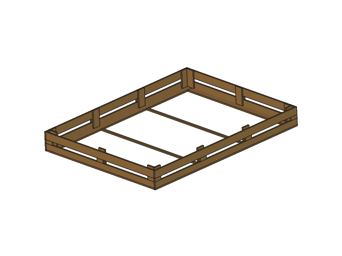
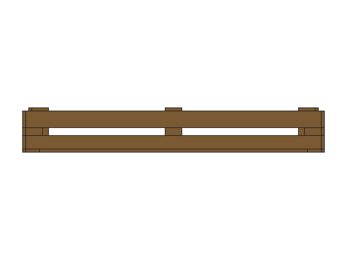
- Lower and upper rims — continuous horizontal bands that tie every wall into one ring; the lower rim spreads the cargo weight into the skids, the upper rim braces the lid.
- Horizontal braces — bottom, middle and top, spaced along the wall height so no span between posts goes unsupported.
- Inner verticals — added automatically where the wall span exceeds a safe unsupported length.
- Slats — the visible skin: vertical or horizontal, in the wall mode you choose.
The engine works in millimetres and assumes the classic pallet-board profile — boards 100 mm wide at a core thickness of 18 mm — unless you specify your own purchased timber and its gross thickness. It computes mitre angles, joint offsets and splice lengths with full geometric precision.
03Wall Modes — Choose Your Skin
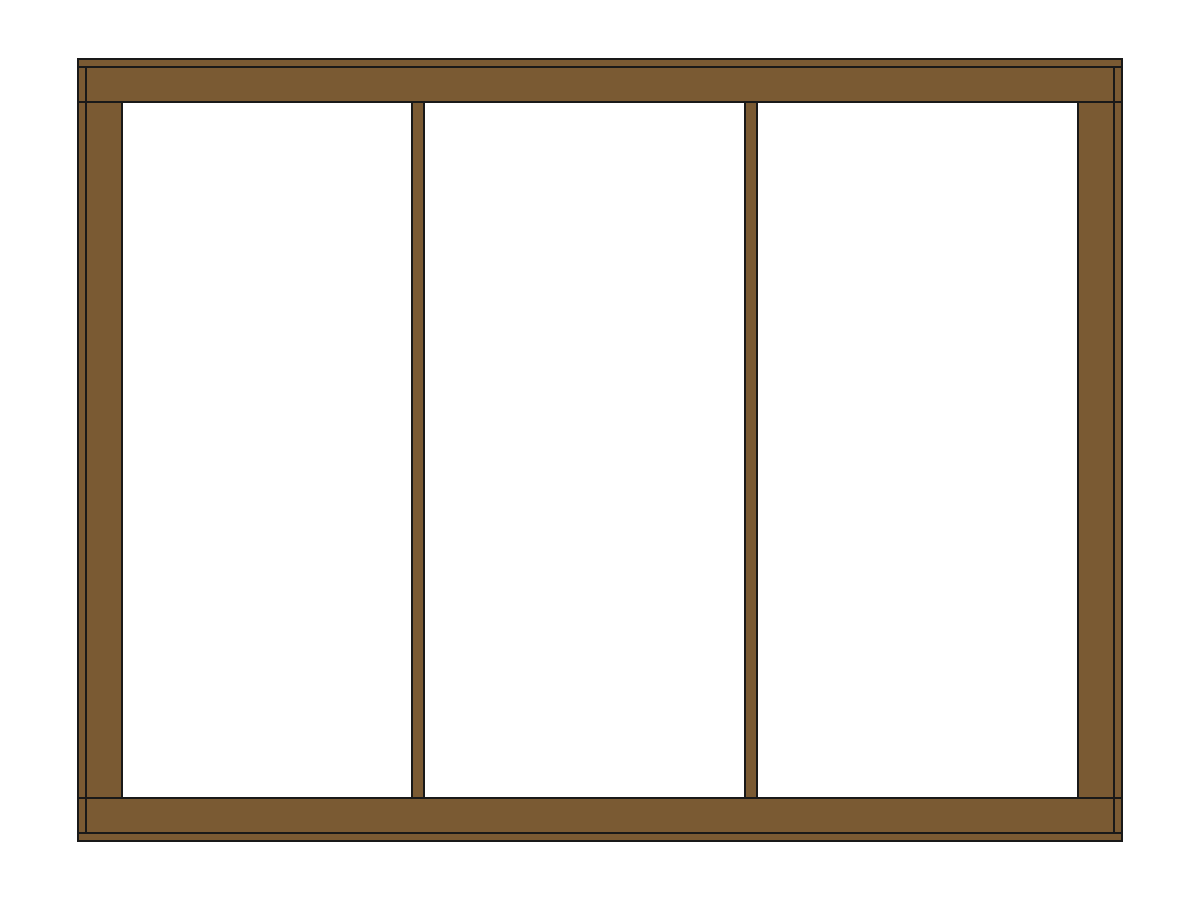
Three construction modes change the skin of every wall:
- Slats only — the classic crate. Vertical or horizontal slats over the open frame. Airflow, economy, easy inspection. Ideal for machinery that benefits from ventilation on the voyage.
- Slats + lining — the “vault box”. Exterior slats plus a solid interior panel lining. Dust-tight and rain-tight, the workhorse of fragile cargo and overseas container shipment.
- Lining only — a completely solid exterior box in plywood or MDF sheet. Maximum sealing and surface smoothness for the most delicate goods.
Combine any mode with your wall orientation (vertical or horizontal slats) and optional X-bracing for heavy loads — the engine places the arms so they reinforce the frame without blocking forklift entries or tie-down points.


04The Forklift Base & Skids
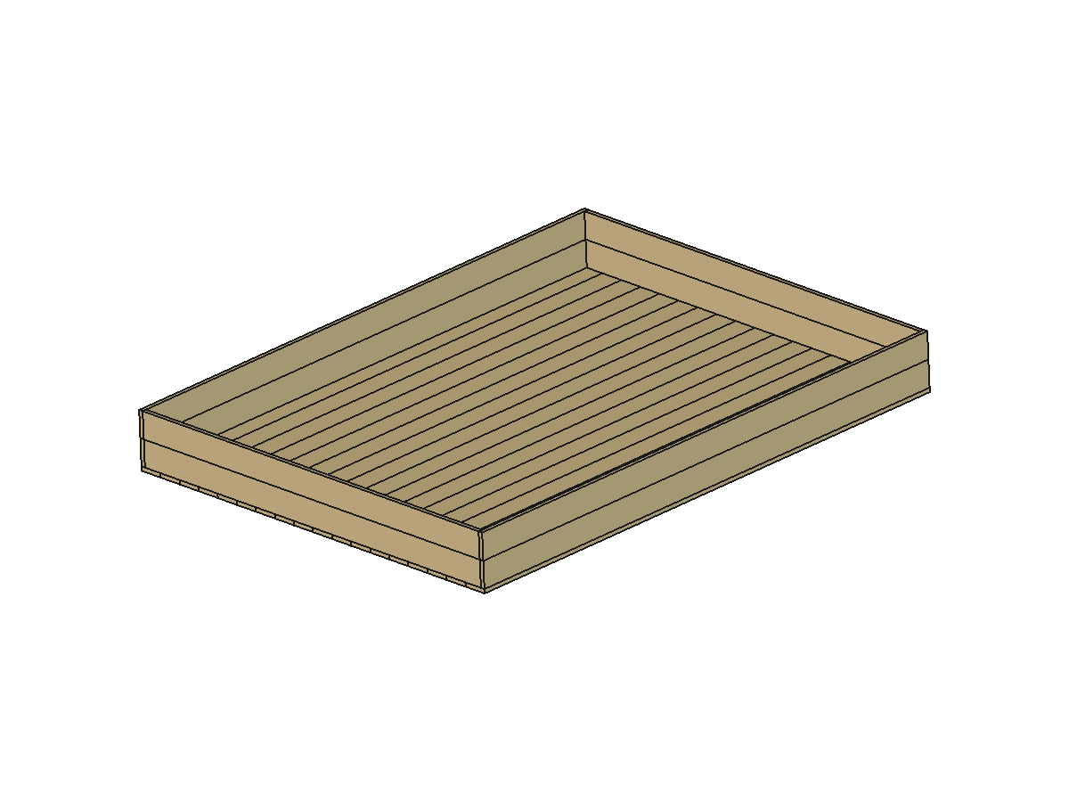
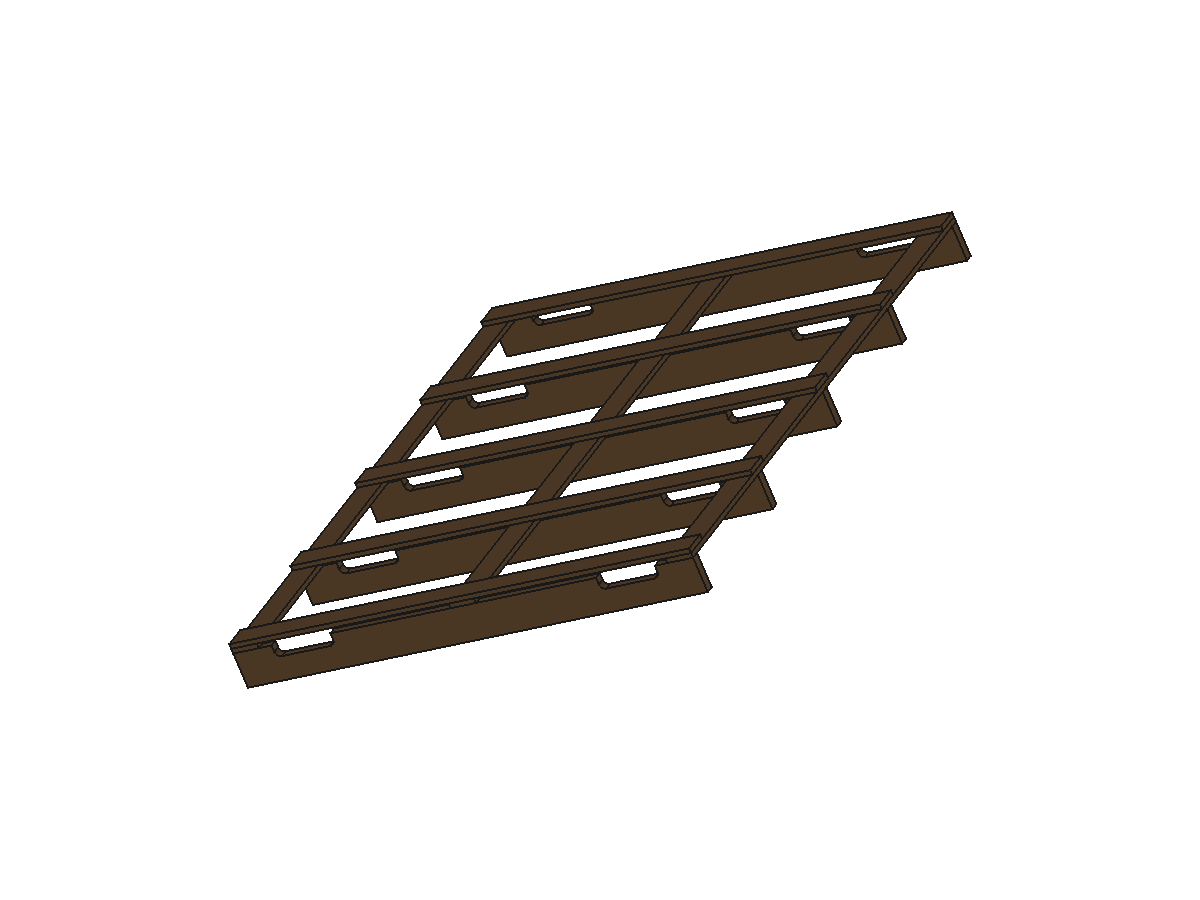
Lifting is where most crates fail, so the base is engineered like a bridge. With the forklift option, the engine lays three solid runners — front edge, centre spine and back edge — each a full frame-width board, with decking arranged so the notch opening stays clear for pallet jacks and forklift tines. The default skid height is 100 mm, enough for most jacks; heavier machinery can request taller skids.
- 4-way access — the tine gaps are computed on all four sides.
- Load spread — the lower rim transfers cargo weight into the three runners evenly.
- Stacking — the skids align with the upper rim so stacked crates bear column-to-column, never on the walls.
05Every Size, From Matchbox to Leviathan
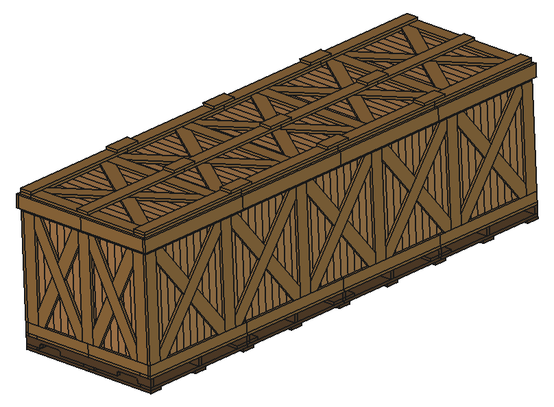
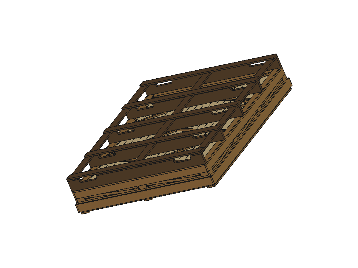
The engine is scale-agnostic. The same solver that designs a micro crate for spare parts also designs a 4.5-metre long hauler — the members, joints and skids simply recompute for the new numbers. Among the twenty showcase designs you will find the full spectrum:
- Matchbox Micro Crate — small-parts shipping, delicate scale kept true.
- Jenga Cube Stack — a perfect cube, stackable with identical siblings.
- MDF Monolith Solid — a sealed monolithic cabinet for clean-room freight.
- Heavy Industrial Titan — 2-tonne-ready, 4-way forklift base.
- Leviathan Long Hauler — extreme length for oversized machinery.
Give us three numbers; the engine gives you the rest.
06Protection & Sealing Guide — Chemical Compounds
A well-built crate still fails if the wood is not prepared for the voyage. Here is the workshop protocol we recommend before any long journey — each step is simple, cheap and transforms a good crate into a watertight one.
Moisture seal — Darawell
Mix Darawell with water at a 1:3 ratio (one part compound, three parts water) and apply generously to every face of the assembled crate — exterior slats, interior lining, rim edges and the cut ends of every board, where moisture enters first. One coat on the interior, two coats on the exterior, and the crate becomes resistant to the humidity of a tropical port, a freezing deck hold or a desert container. Allow 24 hours of drying before loading.
Insect & fungus guard — borate
For long-term storage or routes through tropical regions, dissolve borate powder in water (per the manufacturer's ratio) and apply before the Darawell. Borate penetrates the timber and protects against wood-boring insects and fungal staining — safe, odourless and long-lasting.
Seal the seams — silicone
After the Darawell has cured, run a neutral-cure silicone sealant along the inside corners, the lid seat and the rim joints of a lining-only or slats-and-lining crate. This is the difference between “mostly dry” and “driving rain on the deck” dry.
Cargo-side protection
Line the interior with VCI (volatile corrosion inhibitor) paper for metal cargo, add desiccant packs (1–2 kg per cubic metre of interior volume) for electronics and fabrics, and use closed-cell foam blocking so nothing shifts against the lining. The volumetric analysis in your blueprint tells you exactly how much interior space you have to plan for.
07Loading, Handling & The Journey
- Prepare the base — place a foam or plywood pad over the skid decking.
- Seat the cargo — centred, on blocking, never touching the walls directly.
- Block and tie — screw blocking cleats to the decking and tension ratchet straps through the frame members, not the slats.
- Close the lid — seat it on the upper rim and fasten with corrosion-resistant screws on the computed spacing.
- Mark it — label with weight, “this side up”, and any handling icons; a printed label from your blueprint PDF works perfectly.
- Lift correctly — forklift tines fully inserted; never lift from the slats or a single edge.
08The Blueprint Package
Every transport crate order delivers the full engineering package by email: a permanent save of the parametric viewer from BuildCrates.com, so you can review the shape of your crate online at any time — plus the blueprint PDF with orthographic views and cut lists, all render views and the complete design specification. The moment your Bitcoin payment confirms on the blockchain, the complete package lands in your inbox. See Blueprints for the full breakdown.
09The Size Spectrum — One Solver, Every Scale
The engine has no size classes — it has one solver and three limits (length ≥ 200 mm, width ≥ 100 mm, height ≥ 100 mm). Drag across the showcase below: every dot is a real design the same mathematics produced.
Each bay is capped at 900 mm of clear width, so the engine adds an interior post whenever a wall grows — that is why a 2000 mm wall carries 3 bays, and why a 4500 mm hauler carries 5 down its length. The same rule scales the crate from a matchbox to a machine shed without changing a single joint.
10Design Estimator — Drive the Real Math
This is not a marketing toy — it is the same arithmetic the generator performs on your order: bay subdivision, usable interior, exterior surface, floor pressure against the 400 kg/m² design load and the lateral X-brace tension. Move the sliders and watch the engine think.
Your three numbers
Formula: usable interior = (L−2×(t+t+t)) × (W−2×(t+t+t)) × (H−base−3t) — the engine subtracts core, wall and core on every side. Floor pressure = declared load ÷ usable floor; brace tension = 15% load ÷ brace count × diagonal slope. The generator performs these same steps per order.